No products
To be determined Shipping
$0.00 Total
 View larger
")
3606480966576
New Factory Sealed - Original product -12 Months Warranty
Warning: Last items in stock!
Availability date:

| Frame Type | Altivar 320 |
| Supply Voltage | 200..240V |
| Motor HP | 3 HP |
| Motor Power KW | 2.2 KW |
| Number of Phases | 1 Phase |
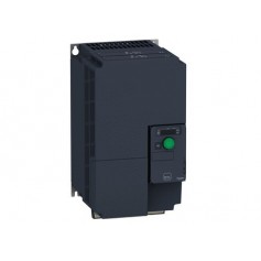
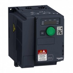
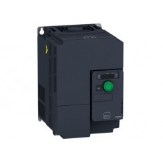
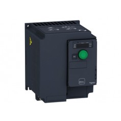
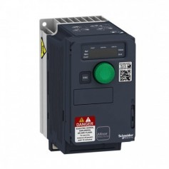
| range of product | Altivar Machine ATV320 | |
|---|---|---|
| product or component type | Variable speed drive | |
| product specific application | Complex machines | |
| device short name | ATV320 | |
| format of the drive | Compact | |
| product destination | Asynchronous motors Synchronous motors | |
| EMC filter | Class C2 EMC filter integrated | |
| IP degree of protection | IP20 conforming to EN/IEC 61800-5-1 | |
| degree of protection | UL type 1 with UL type 1 conformity kit | |
| type of cooling | Fan | |
| network number of phases | 1 phase | |
| [Us] rated supply voltage | 200...240 V (- 15...10 %) | |
| supply frequency | 50...60 Hz (- 5...5 %) | |
| motor power kW | 2.2 kW for heavy duty | |
| motor power hp | 3 hp for heavy duty | |
| line current | 23.9 A at 200 V for heavy duty 20.1 A at 240 V for heavy duty | |
| prospective line Isc | <= 1 kA | |
| apparent power | 4.8 kVA at 240 V for heavy duty | |
| continuous output current | 11 A at 4 kHz for heavy duty | |
| maximum transient current | 16.5 A during 60 s for heavy duty | |
| asynchronous motor control profile | Flux vector control without sensor - Energy Saving Flux vector control without sensor, standard Voltage/frequency ratio - Energy Saving, quadratic U/f Voltage/frequency ratio, 5 points Voltage/frequency ratio, 2 points | |
| synchronous motor control profile | Vector control without sensor | |
| speed drive output frequency | 0.1...599 Hz | |
| nominal switching frequency | 4 kHz | |
| switching frequency | 4...16 kHz with current derating 2...16 kHz adjustable | |
| safety function | STO (safe torque off) SIL 3 SS1 (safe stop 1) SMS (safe maximum speed) SLS (safe limited speed) GDL (guard door locking) | |
| communication port protocol | CANopen Modbus | |
| option card | Communication module: CANopen daisy chain RJ45 Communication module: CANopen SUB-D 9 Communication module: CANopen open style terminal block Communication module: EtherCAT RJ45 Communication module: DeviceNet Communication module: Ethernet/IP Communication module: Profibus DP V1 Communication module: Profinet Communication module: Ethernet Powerlink |
| output voltage | <= power supply voltage | |
|---|---|---|
| permissible temporary current boost | 1.5 x In during 60 s for heavy duty | |
| speed range | 1...100 with asynchronous motor in open-loop mode | |
| speed accuracy | +/- 10 % of nominal slip 0.2 Tn to Tn | |
| torque accuracy | +/- 15 % | |
| transient overtorque | 170...200 % of nominal motor torque | |
| braking torque | <= 170 % with braking resistor during 60 s | |
| regulation loop | Adjustable PID regulator | |
| motor slip compensation | Not available in voltage/frequency ratio (2 or 5 points) Adjustable 0...300 % Automatic whatever the load | |
| acceleration and deceleration ramps | Linear S U Deceleration ramp adaptation CUS Ramp switching Deceleration ramp automatic stop DC injection | |
| braking to standstill | By DC injection | |
| protection type | Drive: thermal protection Drive: overcurrent between output phases and earth Drive: input phase breaks Drive: overheating protection Drive: short-circuit between motor phases | |
| frequency resolution | Display unit: 0.1 Hz Analog input: 0.012/50 Hz | |
| electrical connection | Control, screw terminal: 0.5...1.5 mm² AWG 20...AWG 16 Motor/braking resistor, screw terminal: 6 mm² AWG 10 Power supply, screw terminal: 6 mm² AWG 10 | |
| connector type | 1 RJ45 for Modbus/CANopen on control terminal | |
| physical interface | 2-wire RS 485 for Modbus | |
| transmission frame | RTU for Modbus | |
| transmission rate | 4.8, 9.6, 19.2, 38.4 kbit/s for Modbus 50 kbps, 125 kbps, 250 kbps, 500 kbps, 1 Mbps for CANopen | |
| data format | 8 bits, configurable odd, even or no parity for Modbus | |
| type of polarization | No impedance for Modbus | |
| number of addresses | 1...247 for Modbus 1...127 for CANopen | |
| method of access | Slave for CANopen | |
| supply | Internal supply for reference potentiometer (1 to 10 kOhm): 10.5 V DC (+/- 5 %) current <= 10 mA (overload and short-circuit protection) | |
| local signalling | 1 LED green for CANopen run 1 LED red for CANopen error 1 LED red for drive fault | |
| width | 105 mm | |
| height | 142 mm 188 mm with EMC plate | |
| depth | 158 mm | |
| product weight | 1.6 kg | |
| analogue input number | 3 | |
| analogue input type | Voltage (AI1): 0...10 V DC, impedance 30000 Ohm, resolution 10 bits Bipolar differential voltage (AI2): +/- 10 V DC, impedance 30000 Ohm, resolution 10 bits Current (AI3): 0...20 mA (or 4-20 mA, x-20 mA, 20-x mA or other patterns by configuration), impedance 250 Ohm, resolution 10 bits | |
| discrete input number | 7 | |
| discrete input type | Programmable (sink/source) (DI1...DI4): 24...30 V DC: level 1 PLC Programmable as pulse input 20 kpps (DI5): 24...30 V DC: level 1 PLC Switch-configurable PTC probe (DI6): 24...30 V DC Safe torque off (STO): 24...30 V DC, impedance 1500 Ohm | |
| discrete input logic | Negative logic (sink): : DI1...DI6, > 19 V (state 0) < 13 V (state 1) Positive logic (source): : DI1...DI6, < 5 V (state 0) > 11 V (state 1) | |
| analogue output number | 1 | |
| analogue output type | Software-configurable current (AQ1): 0...20 mA, impedance 800 Ohm, resolution 10 bits Software-configurable voltage (AQ1): 0...10 V, impedance 470 Ohm, resolution 10 bits | |
| sampling duration | Analog input (AI1, AI2, AI3): 2 ms Analog output (AQ1): 2 ms | |
| accuracy | Analog input AI1, AI2, AI3: +/- 0.2 % for a temperature of -10...60 °C Analog input AI1, AI2, AI3: +/- 0.5 % for a temperature of 25 °C Analog output AQ1: +/- 1 % for a temperature of 25 °C Analog output AQ1: +/- 2 % for a temperature of -10...60 °C | |
| linearity error | Analog input (AI1, AI2, AI3): +/- 0.2...0.5 % of maximum value Analog output (AQ1): +/- 0.3 % | |
| discrete output number | 3 | |
| discrete output type | Configurable relay logic NO/NC (R1A, R1B, R1C): electrical durability 100000 cycles Configurable relay logic NO (R2A, R2B): electrical durability 100000 cycles Logic (LO) | |
| refresh time | Logic input (DI1...DI6): 8 ms (+/- 0.7 ms) Relay output (R1A, R1B, R1C): 2 ms Relay output (R2A, R2C): 2 ms | |
| minimum switching current | Relay output (R1, R2): 5 mA at 24 V DC | |
| maximum switching current | Relay output (R1) on resistive load (cos phi = 1: 3 A at 250 V AC Relay output (R1) on resistive load (cos phi = 1: 4 A at 30 V DC Relay output (R1, R2) on inductive load (cos phi = 0.4: 2 A at 250 V AC Relay output (R1, R2) on inductive load (cos phi = 0.4: 2 A at 30 V DC Relay output (R2) on resistive load (cos phi = 1: 5 A at 250 V AC Relay output (R2) on resistive load (cos phi = 1: 5 A at 30 V DC | |
| specific application | Machinery | |
| discrete and process manufacturing | Hoisting self erecting Material handling carousel Material handling conveyor Material handling lifting platfrom Material handling palletizers - medium performance Material handling transfer table Material handling turn table Material working (wood, ceramic, stone, pvc, metal) cutting - medium accuracy Material working (wood, ceramic, stone, pvc, metal) drilling Material working (wood, ceramic, stone, pvc, metal) saw Packaging bagging Packaging feed conveyor low performance Packaging filling bottles - intermittent operation Packaging linear labeling Packaging other application Packaging stretching wrapping Packaging tray take Textile knitting Textile printing machines Textile spinning Washing machines car Washing machines other application Hoisting standard crane - travelling or trolley | |
| power range | 2.2...3 kW 200...240 V 1 phase | |
| motor starter type | Variable speed drive |
| isolation | Between power and control terminals | |
|---|---|---|
| insulation resistance | > 1 mOhm at 500 V DC for 1 minute to earth | |
| noise level | 48 dB conforming to 86/188/EEC | |
| power dissipation in W | 109.6 W (fan) at 200 V, 4 kHz | |
| volume of cooling air | 16 m3/h | |
| operating position | Vertical +/- 10 degree | |
| electromagnetic compatibility | Conducted radio-frequency immunity test conforming to IEC 61000-4-6 level 3 Electrical fast transient/burst immunity test conforming to IEC 61000-4-4 level 4 Electrostatic discharge immunity test conforming to IEC 61000-4-2 level 3 Radiated radio-frequency electromagnetic field immunity test conforming to IEC 61000-4-3 level 3 Voltage dips and interruptions immunity test conforming to IEC 61000-4-11 1.2/50 µs - 8/20 µs surge immunity test conforming to IEC 61000-4-5 level 3 | |
| pollution degree | 2 conforming to EN/IEC 61800-5-1 | |
| vibration resistance | 1.5 mm peak to peak (f = 2...13 Hz) conforming to EN/IEC 60068-2-6 1 gn (f = 13...200 Hz) conforming to EN/IEC 60068-2-6 | |
| shock resistance | 15 gn during 11 ms conforming to EN/IEC 60068-2-27 | |
| relative humidity | 5...95 % without condensation conforming to IEC 60068-2-3 5...95 % without dripping water conforming to IEC 60068-2-3 | |
| ambient air temperature for operation | -10...50 °C without derating 50...60 °C with derating factor | |
| ambient air temperature for storage | -25...70 °C | |
| operating altitude | <= 1000 m without derating 1000...3000 m with current derating 1 % per 100 m | |
| standards | EN/IEC 61800-3 EN/IEC 61800-3 environment 1 category C2 EN/IEC 61800-5-1 IEC 60721-3 IEC 61508 IEC 13849-1 | |
| product certifications | EAC UL CSA RCM NOM 117 | |
| marking | CE |
| Sustainable offer status | Green Premium product | |
|---|---|---|
| RoHS (date code: YYWW) | Compliant - since 1610 - Schneider Electric declaration of conformity Schneider Electric declaration of conformity | |
| REACh | ||
| Product environmental profile | AvailableProduct environmental | |
| Product end of life instructions | AvailableProduct environmental |